TM1637 7-Segment Display
The tm1637 display platform allows you to use the popular TM1637 7-segment display drivers with ESPHome.
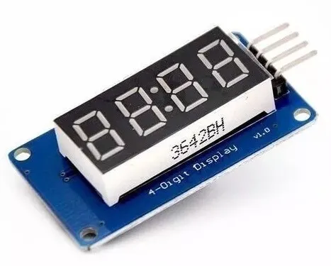
The module can be powered with 5v or with 3.3v too. To display the colon punctuation use the
. in the colon place. (See clock example below)
# Example configuration entrydisplay: platform: tm1637 id: tm1637_display clk_pin: D6 dio_pin: D5 inverted: true length: 4 lambda: |- it.print("0123");Configuration variables
Section titled “Configuration variables”-
clk_pin (Required, Pin Schema): The pin you have the CLK line hooked up to.
-
dio_pin (Required, Pin Schema): The pin you have the DIO line hooked up to.
-
intensity (Optional, int): The intensity with which the TM1637 should drive the outputs. Range is from 0 (least intense) to 7 (the default).
-
inverted (Optional, bool): Invert character rendering to the TM1637 so you can physically flip the display around.
-
length (Optional, int): The amount of digits your TM1637 is driving. Only used when
inverted: trueRange is from 1 to 6 (the default). -
lambda (Optional, lambda): The lambda to use for rendering the content on the TM1637. See Rendering Lambda for more information.
-
update_interval (Optional, Time): The interval to re-draw the screen. Defaults to
1s. -
id (Optional, ID): Manually specify the ID used for code generation.
Binary Sensor
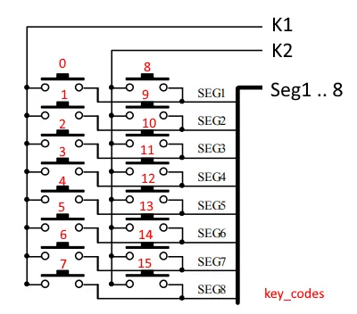
Section titled “Binary Sensor”The TM1637 LED display controller also includes a special circuit with keyboard scan interface and enhanced identification circuit with anti-interference keys. This circuit uses the 8 segment lines that also drive the LED display. But combined with the K1 and K2 pins we can add 16 keys that can be used as binary sensors in esphome.
binary_sensor: - platform: tm1637 id: key0 name: key1-00 tm1637_id: tm1637_display key: 0Configuration variables
Section titled “Configuration variables”-
id (Optional, ID): Set the ID of this sensor.
-
name (Optional, string): The name for the binary sensor.
-
tm1637_id (Optional, :ID): The id of the tm1637 that should be used to scan the keys in case you are using multiple devices.
-
key (Required, integer): The keycode for the connected key (Seg0 = 0, Seg1 = 1 etc,). Range is from 0 to 15.
-
All other options from Binary Sensor.
Rendering Lambda
Section titled “Rendering Lambda”The TM1637 has a similar API to the fully fledged Display Rendering Engine, but it’s only a subset as the TM1637
7-segment displays don’t have a concept of individual pixels. In the lambda you’re passed a variable called it
as with all other displays. In this case however, it is a TM1637 instance (see API Reference).
The most basic operation with the TM1637 is writing a simple number to the screen as in the configuration example
at the top of this page. But even though you’re passing in a string (here "0123" ), ESPHome converts it
into a representation that the TM1637 can understand: The exact pixels that should be turned on. And of course,
not all characters can be represented. You can see a full list of characters at the MAX7219 docs.
Each of the three methods (print, printf and strftime ) all optionally take a position argument at the
beginning which can be used to print the text at a specific position. This argument is 0 by default which
means the first character of the first TM1637. For example to start the first character of your text at
the end of the TM1637, you would write it.print(3, "0");.
Also note that the . (dot) character is special because when ESPHome encounters it in the string the dot
segment of the previous position will be enabled.
display:  - platform: tm1637    # ...    lambda: |-      // Print 0 at position 0 (left)      it.print("0");      // Result: "0   "
      // Print 1 at position 1 (second character)      it.print(1, "1");      // Result: "01  "
      // Let's write a sensor value (let's assume it's 42.1)      it.printf(0, "%.1f", id(my_sensor).state);      // Result: "42.1 " (the dot will appear on the "2" segment)
      // Overwrite the previous content with blank      it.print("    ");      // Print a right-padded sensor value with 0 digits after the decimal      it.printf("S%3.0f", id(my_sensor).state);      // Result: "S 42"
      // Print the current time      it.strftime("%H.%M", id(homeassistant_time).now());      // Result for 10:06:42 -> "10:06" on a display with : and "10.06" on a display with .
Please see Formatted Text for a quick introduction into the printf formatting rules and
Displaying Time for an introduction into the strftime time formatting.
Creating a digital clock
Section titled “Creating a digital clock”The following example creates a typical digital clock with the : colon flashing every second.
time:  - platform: homeassistant    id: homeassistant_time
display:  platform: tm1637  clk_pin: D6  dio_pin: D5  update_interval: 500ms  lambda: |-      static int i = 0;      i++;      if ((i % 2) == 0)        it.strftime("%H.%M", id(homeassistant_time).now());      else        it.strftime("%H%M", id(homeassistant_time).now());
Raw segment buffer
Section titled “Raw segment buffer”If you already have segment bitmasks, you can write raw bytes directly to the display buffer using set_buffer. This
bypasses character conversion and is useful for custom glyphs or animations.
void set_buffer(const uint8_t *data, uint8_t length);- data: Pointer to an array of segment bytes, one byte per digit.
- length: Number of bytes to write (should not exceed the number of digits).
The TM1637 uses a single byte per digit where each bit maps to a segment (a–g). The decimal point is bit 7 (0x80).
display: - platform: tm1637 # ... lambda: |- // Raw segment values for "0123" with the dot on digit 3 static const uint8_t buf[] = {0x3f, 0x06, 0x5b, 0x4f | 0x80}; it.set_buffer(buf, sizeof(buf));Connect multiple displays
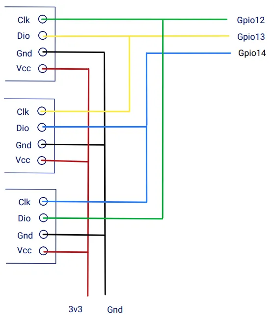
Section titled “Connect multiple displays”To connect multiple TM1636 displays you need as many control lines as you have displays. This is achived by sharing control-lines for clk and dio between displays.
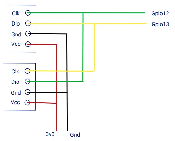
When using the pins more than once, the configuration must reflect the fact:
display:  - platform: tm1637    id: lcd1    clk_pin:      number: GPIO3      allow_other_uses: true    dio_pin:      number: GPIO4      allow_other_uses: true
  - platform: tm1637    id: lcd2    clk_pin:      number: GPIO4      allow_other_uses: true    dio_pin:      number: GPIO3      allow_other_uses: true
When using more than 2 devices like 3 or more you add a control-line for the Dio pin and share this with the next display Clk pin. The last displays Dio pin shares the Clk pin of the first display.