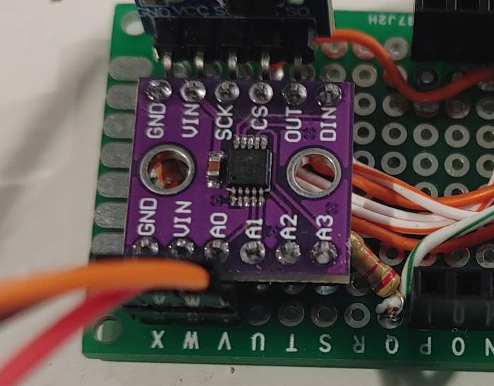
ADS1118 4-Channel 16-Bit A/D Converter with Internal Temperature Sensor
Component/Hub
ADS1118 4-Channel 16-Bit A/D Converter (datasheet)
The ads1118 domain creates a global hub so that you can later create
individual sensors using the ADS1118 Sensor Platform.
It uses the SPI Bus for communication.

ads1118:
  cs_pin: GPIOXX
Configuration variables
- cs_pin (Required, int): The SPI cable select pin to use.
- id (Optional, ID): Manually specify the ID for this ADS1118 Hub. Use this if you want to use multiple ADS1118 hubs at once.
Sensor
The ads1118 sensor allows you to use your ADS1118 delta-sigma ADC
sensors (datasheet) with ESPHome.
First, setup an ADS1118 Hub for your ADS1118 sensor and then use this
sensor platform to create individual sensors that will report the voltage.
sensor:
  - platform: ads1118
    type: adc
    id: batt_volt
    name: Battery Voltage
    multiplexer: A3_GND
    gain: 4.096
    update_interval: .01s
Configuration variables
type (Optional):
adc(default) ortemperatureads1118_id (Optional, ID): Manually specify the ID of the ADS1118 Hub you want to use this sensor.
update_interval (Optional, Time): The interval to check the sensor. Defaults to
60s.All other options from Sensor.
ADC Options
- multiplexer (Required): The multiplexer channel of this sensor. Effectively means between which pins you want to measure voltage.
- gain (Required, float): The gain of this sensor.
Temperature Options
None
Multiplexer and Gain
ℹ️ Note
As per (datasheet) Section 7.3 Note 2: “No more than VDD + 0.3V must be applied to the analog inputs of the device.” This means if you power the device with 3.3V, take care not to supply the 4 AIN pins with more than 3.6V.
The ADS1118 has a multiplexer that can be configured to measure voltage between several pin configurations. These are:
A0_A1(between Pin 0 and Pin 1)A0_A3(between Pin 0 and Pin 3)A1_A3(between Pin 1 and Pin 3)A2_A3(between Pin 2 and Pin 3)A0_GND(between Pin 0 and GND)A1_GND(between Pin 1 and GND)A2_GND(between Pin 2 and GND)A3_GND(between Pin 3 and GND)
Additionally, the ADS1118 has a Programmable Gain Amplifier (PGA) that can help you measure voltages in different ranges, these are:
6.144(measures up to 6.144V)4.096(measures up to 4.096V)2.048(measures up to 2.048V)1.024(measures up to 1.024V)0.512(measures up to 0.512V)0.256(measures up to 0.256V)

