Power Supply Component
The power_supply component allows you to have a high power mode for
certain outputs. For example, if you’re using an ATX powersupply to power your LED strips,
you usually don’t want to have the power supply on all the time while
the output is not on. The power supply component can be attached to any
Output Component and
will automatically switch on if any of the outputs are on. Furthermore,
it also has a cooldown time that keeps the power supply on for a while
after the last output has been disabled.
# Example configuration entrypower_supply: - id: 'power_supply1' pin: GPIOXXConfiguration variables
Section titled “Configuration variables”-
id (Required, ID): The id of the power supply so that it can be used by the outputs.
-
pin (Required, Pin Schema): The GPIO pin to control the power supply on.
-
enable_time (Optional, Time): The time that the power supply needs for startup. The output component will wait for this period of time after turning on the PSU and before switching the output on. Defaults to
20ms. Maximum of less than5s. -
keep_on_time (Optional, Time): The time the power supply should be kept enabled after the last output that used it has been switch off. Defaults to
10s. -
enable_on_boot (Optional, bool): If the power supply should be enabled when the power supply component is setup. Defaults to false. The startup delay will be applied (other component setup will be blocked until the delay has elapsed.) This is useful for power supplies that will never be turned off and avoids the need to specifically configure the power supply in a different component.
See the output component base configuration for information on how to apply the power supply for a specific output.
ATX Power Supplies
Section titled “ATX Power Supplies”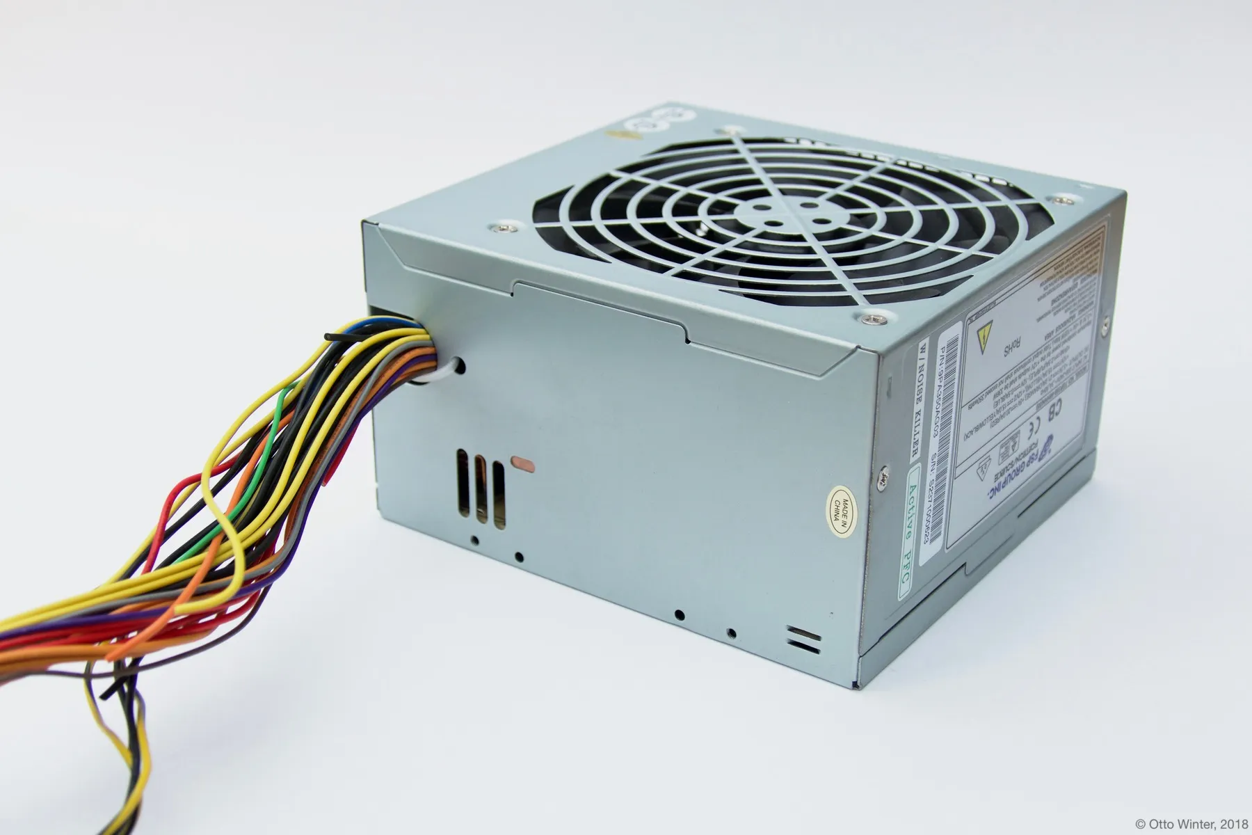
The power supply component will default to pulling the specified GPIO pin up when high power mode is needed. Most ATX power supplies however operate with an active-low configuration. Therefore their output needs to be inverted.
power_supply: - id: 'atx_power_supply' pin: number: 13 inverted: trueThen simply connect the green control wire from the ATX power supply to your specified pin. It’s recommended to put a small resistor (about 1kΩ) in between to protect the ESP board.