1-Wire Bus
The one_wire component allows you to use supported 1-Wire devices in ESPHome.
Hardware
Section titled “Hardware”The 1-Wire bus the devices are connected to should have an external pull-up resistor of about 4.7KΩ. A resistor of
about 4.7KΩ connected between 3.3V and the 1-Wire bus’s GPIO/data pin should suffice. Values ± 1KΩ will generally
work fine as well, provided you don’t have unusually long wires.
Platforms
Section titled “Platforms”Obtaining Sensor IDs
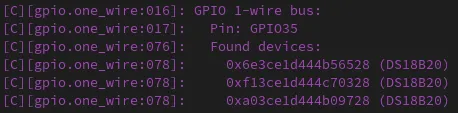
Section titled “Obtaining Sensor IDs”To find device addresses, simply start the firmware on your device with a one_wire hub configured and observe the
log output. Note that you don’t need to define the individual sensors just yet, as scanning will occur even with no
sensors configured.
Here’s an example log: