WeiKai SPI/I²C UART/IO Expander
WeiKai Microelectronics provides a family of UART & GPIO expansion chips that interfaces to a micro-controller through SPI or I²C bus.
The ESPHome WeiKai component supports the following WeiKai chips:
It can also be used with evaluation board equipped with these chips, such as:
- WK2168 Chip Development Board
- WK2132 Chip Development Board
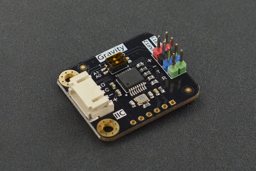
- DFROBOT Gravity: I²C to Dual UART Module
The features provided by the different WeiKai chips are described in the following table:
WeiKai chip’s features
Section titled “WeiKai chip’s features”| Chip | Bus | UART | GPIO |
|---|---|---|---|
| WK2132-ISSG | S/I | 2 | |
| WK2212-IQNG | S/I | 2 | 8 |
| WK2124-ISSG | S | 4 | |
| WK2204-IQNG | S/I | 4 | |
| WK2168-IQPG | S/I | 4 | 8 |
As you can see most of the components can interface either through an I²C bus or a SPI bus, they provide either 2 or 4 serial channels, and some provide 8 input/output pins.
Each UART channel has two independent 256-byte FIFO hardware buffers to transmit and receive and support data transmission rates up to 1 Mbps. The baud rate and parity format of each UART channel can be configured independently. However, the data bit length is fixed at 8.
Utilizing the UART channels enables you to connect your UART devices, with each channel functioning as a virtual UART bus for the connected component.
The I/O pins of the WeiKai chips can be use as any of the other GPIO pins. Any option accepting a Pin Schema can theoretically be used, but some more complicated components that do communication through this I/O expander might not work.
Connecting via an SPI bus
Section titled “Connecting via an SPI bus”The wk2132_spi, wk2212_spi, wk2204_spi, wk2168_spi components allows
you to connect the WeiKai chip with ESPHome via a SPI bus.
You can connect several of these modules to a single SPI controller circuit effectively expanding the number of hardware serial ports available. Each WeiKai chip needs to be selected with a individual CS.
Here is an example of configuration entry for a wk2168_spi component. For the other components
in the list just replace the name of the component and make sure you do not use more channels that the chip
can support (an error message will be generated otherwise). Note that for the WK2124-ISSG chip
you need to use wk2204_spi as the two chips are similar.
wk2168_spi: - id: wk2168_bridge_spi cs_pin: 5 uart: - id: spi_uart_0 channel: 0 baud_rate: 128200 parity: even - id: spi_uart_1 channel: 1 baud_rate: 19200 - id: spi_uart_2 channel: 2 baud_rate: 9600 - id: spi_uart_3 channel: 3 baud_rate: 19200Configuration variables
Section titled “Configuration variables”-
id (Required, ID): The id to use for this WeiKai component.
-
spi_id (Optional, ID): Manually specify the ID of the SPI Component if you want to use multiple SPI buses.
-
cs_pin (Required, Pin Schema): The pin on the ESP that the chip select line of the chip is connected to.
-
data_rate (Optional): Set the data rate of the controller. One of
80MHz,40MHz,20MHz,10MHz,5MHz,4MHz,2MHz,1MHz(default),200kHz,75kHzor1kHz. A numeric value in Hz can alternatively be specified. -
crystal (Optional): The frequency in Hz of the crystal connected to the chip. The default value is 14745600 Hz.
-
uart (Required): The UART channels.
-
id (Required, ID): The id to use for this UART channel.
-
channel (Required): Unique channel number of this virtual UART. Options:
0to1or0to3depending on the model. -
baud_rate (Required): The baud rate of the UART channel.
-
parity (Optional): The parity used on the UART channel. Options:
NONE,EVEN,ODD. Defaults toNONE. -
stop_bits (Optional): The number of stop bits to send. Options:
1,2. Defaults to1.
-
Connecting via an I²C bus
Section titled “Connecting via an I²C bus”The wk2132_i2c wk2212_i2c wk2204_i2c wk2168_i2c components allows you
to connect the WeiKai chip with ESPHome via an I²C bus.
Up to four WeiKai chips can be connected to an I²C controller board, effectively expanding the
available hardware serial ports. The base addresses of these boards are defined by the
positions of two switches, A0 and A1, on the board.
WeiKai address selection
Section titled “WeiKai address selection”| I²C address | A1 | A0 |
|---|---|---|
| 0x10 - 0x17 | 0 | 0 |
| 0x30 - 0x37 | 0 | 1 |
| 0x50 - 0x57 | 1 | 0 |
| 0x70 - 0x77 | 1 | 1 |
IMPORTANT
Note that the address is given as a range a not a number as you usually find on other I²C component. Indeed due to a peculiar way of addressing the different internal registers each component actually occupy 8 consecutive addresses. For example if the component base address is 0x10, it will occupy the addresses ranging from 0x10 to 0x17 on the I²C bus.
This is important to know if you want to connect other devices on the same I²C bus.
Here is an example of configuration entry for a wk2168_i2c component. For the other components
just replace the name of the component and do not use more channels that the chip can
support (an error message will be generated in this case).
wk2168_i2c: - address: 0x70 id: wk2168_bridge_i2c uart: - id: i2c_uart_0 channel: 0 baud_rate: 9600 parity: even - id: i2c_uart_1 channel: 1 baud_rate: 19200 - id: i2c_uart_2 channel: 2 baud_rate: 9600 - id: i2c_uart_3 channel: 3 baud_rate: 19200Configuration variables
Section titled “Configuration variables”-
id (Required, ID): The id to use for this WeiKai component.
-
address (Optional): The I²C address of this component. Defaults to
0x10. -
i2c_id (Optional): The I²C Bus ID. Defaults to the default i²c bus.
-
crystal (Optional): The frequency in Hz of the crystal connected to the chip. The default value is 14745600 Hz.
-
uart (Required): The UART channels.
-
id (Required, ID): The id to use for this UART channel.
-
channel (Required): Unique channel number of this virtual UART. Options:
0to1or0to3depending on the model. -
baud_rate (Required): The baud rate of the UART channel.
-
parity (Optional): The parity used on the UART channel. Options:
NONE,EVEN,ODD. Defaults toNONE. -
stop_bits (Optional): The number of stop bits to send. Options:
1,2. Defaults to1.
-
Using the GPIO pins
Section titled “Using the GPIO pins”For the WK2212, and WK2168 it is possible to use the chip I/O pins as any of the other GPIO pins.
For example for a wk2168_spi chip:
# individual binary_sensor inputsbinary_sensor:  - platform: gpio    name: "pin_0"    pin:      wk2168_spi: wk2168_bridge_spi      number: 0      mode:        input: true  - platform: gpio    name: "pin_1"    pin:      wk2168_spi: wk2168_bridge_spi      number: 1      mode:        input: true      inverted: true
# Individual binary outputsswitch:  - platform: gpio    name: "pin_2"    pin:      wk2168_spi: wk2168_bridge_spi      number: 2      mode:        output: true  - platform: gpio    name: "pin_3"    pin:      wk2168_spi: wk2168_bridge_spi      number: 3      mode:        output: true      inverted: true
Pin configuration variables
Section titled “Pin configuration variables”-
wkxxxx_xxx (Required, ID): The id of the
wkxxxx_xxxcomponent for the pin. For examplewk2212_i2c: wk2168_bridge_spi -
number (Required): The pin number (
0to7) -
inverted (Optional): If all read and written values should be treated as inverted. Defaults to
false. -
mode (Optional): A pin mode to set for the pin at. One of
INPUTorOUTPUT. Default toINPUT
Performance considerations
Section titled “Performance considerations”Bus speed
Section titled “Bus speed”Please be aware that the communication between the WeiKai chips and the processor occurs on an external bus, with a relatively low operating frequency. Therefore tasks such as checking the status of the chip’s registers or transferring bytes from the internal FIFOs to the processor may take time.
To improve this situation, it is strongly recommended to increase the default bus frequency.
- With a SPI bus this can be done on the WeiKai component by specifying
data_rate. For example:
wk2168_spi: - id: wk2168_bridge_spi spi_id: spi_bus_id cs_pin: 5 data_rate: 4MHz- With an I²C bus this needs to be done on the
i2cdeclaration and therefore this frequency will apply to all components connected to this bus.
i2c: sda: 21 scl: 22 scan: true id: bus_i2c frequency: 800kHzMaximum Baud rate
Section titled “Maximum Baud rate”The maximum baud_rate is proportional to the crystal frequency. The following table gives the maximum baud_rate at usual system clock:
maximum baud rate
Section titled “maximum baud rate”| Clock | Max Bd |
|---|---|
| 14,745,600 Hz | 921,600 Bd |
| 11,059,200 Hz | 691,200 Bd |
| 7,372,800 Hz | 460,800 Bd |
| 3,686,400 Hz | 230,400 Bd |
| 1,843,200 Hz | 115,200 Bd |
If you try to use a baud rate superior to the maximum baud_rate an error will be displayed in the log file and the baud rate will automatically be decreased.