VBus Component
The VBus Component provides status reading connectivity to solar heat energy collector controllers using VBus
protocol. These devices are mainly produced by Resol, often also found under different brand names like Viessmann,
Kioto, Wagner etc. The component currently supports natively the models in the table below
but any device can be added via lambda by knowing its packet structure.

Supported Models
Section titled “Supported Models”The following table shows the currently supported models of Vbus devices.
Supported Models
Section titled “Supported Models”| Name | Config Value | Hex Address | Notes |
|---|---|---|---|
| DeltaSol BS Plus | deltasol_bs_plus | 4221 | |
| DeltaSol BS 2009 | deltasol_bs_2009 | 427B | DeltaSol BS Plus V2 |
| DeltaSol BS/2 (DrainBack) | deltasol_bs2 | 4278 | |
| Dux H3214 | deltasol_bs_2009 | 427B | Pump 2 unsupported |
| DeltaSol C | deltasol_c | 4212 | |
| DeltaSol CS2 | deltasol_cs2 | 1121 | |
| DeltaSol CS4 | deltasol_cs4 | 1122 | Citrin Solar CS 1.3 |
| DeltaSol CS Plus | deltasol_cs_plus | 2211 |
The Config Value should be used for the model parameter in your sensor and binary_sensor entries.
The Hex Address field is the value sent by a device in the from field of a message. To identify an unknown
model, set the logger level to VERBOSE and look for lines like this in the log output:
[10:53:48][V][vbus:068]: P1 C0500 427b->0000: 0000 0000 (0)
The value before the -> symbol is the device source address. If it matches one of the entries in the table above
then that model should work with your unit.
Hardware Connection
Section titled “Hardware Connection”The device must be connected via a UART bus supporting the receiving line only. The UART bus must be configured at the same speed of the module which is by default 9600bps. The controller outputs data every second.
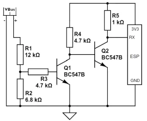
To connect to this and read data from the bus a level shifting is needed as the voltage is around 8V (direct connection would damage the MCU). For our read-only purposes it’s sufficient to adapt the level appropriately to 3.3V using a circuit like below:
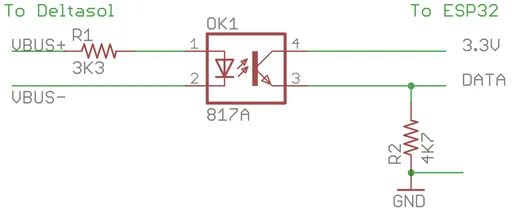
An electrically isolated version using an opto-coupler:
Another approach, with PCB design ready to be manufactured can be found here.
WARNING
Do not connect the GND pin of your module with the ground of Resol unit as that may damage the output port of it. The output of the device is symmetric, meaning that the signal is not referenced to the ground, but rather it’s a differential signal between the two wires. However, the MCU references the signal against the ground, so the two grounds are not supposed to be connected to each other as can be seen in the circuit depicted above.
Component
Section titled “Component”# Example configuration entryvbus: uart_id: resolWARNING
If you are using the Logger make sure you are not using the same pins for it or otherwise disable the UART
logging with the baud_rate: 0 option.
Configuration variables
Section titled “Configuration variables”- uart_id (Optional, ID): Manually specify the ID of the UART hub used to connect to the device.
NOTE
Functionality of the sensors depends on the type of the device and the scheme arrangement of the hydraulic system it controls. The actual arrangement number set up can be determined from the settings of the device. Please check the user manual and assess your arrangement to determine the functionality of each sensor and name them accordingly.
Sensor
Section titled “Sensor”# Example configuration entrysensor: - platform: vbus model: deltasol_bs_plus temperature_1: name: Temperature 1 temperature_2: name: Temperature 2 temperature_3: name: Temperature 3 temperature_4: name: Temperature 4 pump_speed_1: name: Pump Speed 1 pump_speed_2: name: Pump Speed 2 operating_hours_1: name: Operating Hours 1 operating_hours_2: name: Operating Hours 2 heat_quantity: name: Heat Quantity time: name: Device Time version: name: Device firmware versionConfiguration variables
Section titled “Configuration variables”- model (Required): Specify the model of the connected controller. Choose one of the config values listed in the table of supported models above.
Supported sensors:
- for deltasol_bs_plus and deltasol_bs_2009:
temperature_1,temperature_2,temperature_3,temperature_4,pump_speed_1,pump_speed_2,operating_hours_1,operating_hours_2,heat_quantity,time,version. - for deltasol_bs2:
temperature_1,temperature_2,temperature_3,temperature_4,pump_speed_1,pump_speed_2,operating_hours_1,operating_hours_2,heat_quantity,version. - for deltasol_c:
temperature_1,temperature_2,temperature_3,temperature_4,pump_speed_1,pump_speed_2,operating_hours_1,operating_hours_2,heat_quantity,time. - for deltasol_cs2:
temperature_1,temperature_2,temperature_3,temperature_4,pump_speed,operating_hours,heat_quantity,version. - for deltasol_cs4:
temperature_1,temperature_2,temperature_3,temperature_4,temperature_5,pump_speed_1,pump_speed_2,operating_hours_1,operating_hours_2,heat_quantity,time,version,flow_rate. - for deltasol_cs_plus:
temperature_1,temperature_2,temperature_3,temperature_4,temperature_5,pump_speed_1,pump_speed_2,operating_hours_1,operating_hours_2,heat_quantity,time,version,flow_rate.
All sensors are Optional and support all other options from Sensor.
NOTE
Sensors are updated every time a data packet is sent by the device. Some models send data very often, possibly every second. If you are
concerned about the load on the receiving database, you can add a throttle filter to the sensors.
Binary Sensor
Section titled “Binary Sensor”# Example configuration entrybinary_sensor: - platform: vbus model: deltasol_bs_plus relay1: name: Relay 1 On relay2: name: Relay 2 On sensor1_error: name: Sensor 1 Fault sensor2_error: name: Sensor 2 Fault sensor3_error: name: Sensor 3 Fault sensor4_error: name: Sensor 4 Fault collector_max: name: Option Collector Max collector_min: name: Option Collector Min collector_frost: name: Option Collector Frost tube_collector: name: Option Tube Collector recooling: name: Option Recooling hqm: name: Option Heat Quantity MeasurementConfiguration variables
Section titled “Configuration variables”-
model (Required): Specify the model of the connected controller. Choose one of the config values listed in the table of supported models above.
Supported models:
deltasol_bs_plus:relay1,relay2,sensor1_error,sensor2_error,sensor3_error,sensor4_error,collector_max,collector_min,collector_frost,tube_collector,recooling,hqm.deltasol_bs_2009:sensor1_error,sensor2_error,sensor3_error,sensor4_error,frost_protection_active.deltasol_bs2:sensor1_error,sensor2_error,sensor3_error,sensor4_error.deltasol_c:sensor1_error,sensor2_error,sensor3_error,sensor4_error.deltasol_cs2:sensor1_error,sensor2_error,sensor3_error,sensor4_error.deltasol_cs4:sensor1_error,sensor2_error,sensor3_error,sensor4_error.deltasol_cs_plus:sensor1_error,sensor2_error,sensor3_error,sensor4_error.custom: See below.
All binary sensors are Optional and support all other options from Binary Sensor.
custom VBus sensors
Section titled “custom VBus sensors”Devices on a VBus are identified with a source address. There can be multiple devices on the same bus, each device type has a different address.
sensor: - platform: vbus model: custom dest: 0x10 source: 0x1234 command: 0x100 sensors: - id: temp1 name: Temp 1 lambda: return ((x[1] << 8) + x[0]) / 10.0;Configuration variables
Section titled “Configuration variables”-
dest (Optional): The
DFAvalue corresponding to your device (see below). -
source (Optional): The address corresponding to
your device model(see below). -
command (Optional): The
commandcorresponding to your device (see below). -
sensors (Optional): A list of Sensor definitions that include a
lambdato do the decoding and return afloatvalue. -
lambda (Required, lambda): Code to parse a value from the incoming data packets and return it. The data packet is in a
std::vector<uint8_t>calledx.
custom VBus binary sensors
Section titled “custom VBus binary sensors”Configuration variables
Section titled “Configuration variables”-
dest (Optional): The
DFAvalue corresponding to your device (see below). -
source (Optional): The address corresponding to
your device model(see below). -
command (Optional): The
commandcorresponding to your device (see below). -
binary_sensors (Optional): A list of Binary Sensor definitions that include a
lambdato do the decoding and return aboolvalue. -
lambda (Required, lambda): Code to parse a value from the incoming data packets and return it. The data packet is in a
std::vector<uint8_t>calledx.
To determine the correct values for the parameters above, visit packet definitions list. In the search field of the Packets table, enter the name of your device.
To extract the values with a lambda, look in the packet structure by clicking the Bytes link in the table. Each value is placed at an offset within the packet.
For float values, let’s look at the temperature example: the value is stored as a 16 -bit value in 2 bytes little-endian format. Since it’s always the second byte containing the upper byte, it needs to be shifted by 8 bits (multiplied by 256 ) (e.g. 0x34, 0x12 -> 0x1234 ). The result needs to be multiplied by the factor, which is 0.1, to obtain the correct values: ((x[1] << 8) + x[0]) * 0.1f). The number within the square brackets is the [offset].
For binary values, multiple binary values are stored within a single numeric value encoded with a bitmask. To extract the binary value all you have to do is to apply bitwise AND operator & between the value at the corresponding offset and the mask shown in the table.
For example to decode some sensors of DeltaSol BS Plus via lambdas:
# Example configuration entrysensor:  - platform: vbus    model: custom    dest: 0x10    source: 0x4221    command: 0x100    sensors:      - id: scheme        name: Arrangement scheme        icon: mdi:pipe-wrench        accuracy_decimals: 0        entity_category: diagnostic        lambda: return x[14];  // Configured arrangement scheme      - id: temp2        name: Temperature DHW        state_class: measurement        unit_of_measurement: "°C"        lambda: return ((x[3] << 8) + x[2]) * 0.1f;  // Temperature 2
binary_sensor:  - platform: vbus    model: custom    dest: 0x10    source: 0x4221    command: 0x100    binary_sensors:      - name: Heat Quantity Measurement On        id: bin_hqm        icon: mdi:counter        lambda: return x[15] & 0x20; // Option Heat Quantity Measurement enabled